 Save Area
- General Overview
- Step-By-Step
- Tips and Tricks
- Related Tools
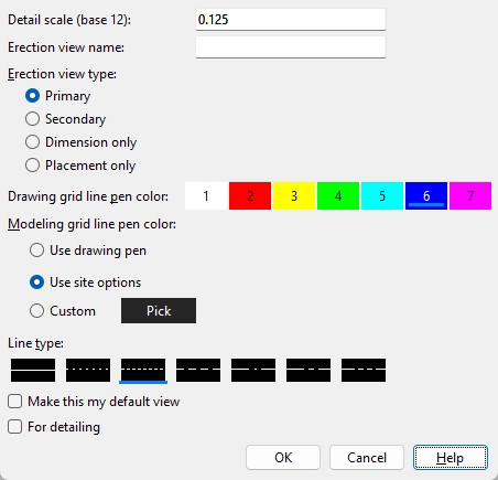
Detail scale (Base 12 (Imperial) or Base 10 (Metric): The entry you make here is the default scale of the 2D erection view drawing of this new view you are creating -- it does not affect the scale of your current view. The default scale set in this window is the Display Options > Drawing scale for your current erection view (the view you are creating this view from). Subsequent versions of the drawing detailed from this view will use the scale entered for this drawing in the Drawing Editor to File > Drawing Data > Drawing scale.
Erection view name: Any text string of up to 61 characters that you want to use as the name for this view. Unless you want this view to overwrite an existing erection view, you should give this view an original name that has not been given to other views.
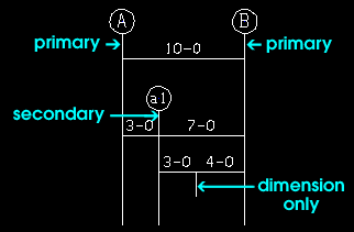
Erection view type: Primary or Secondary or Dimension only or Placement only. The selection you make here sets how the grid line (erection view) is to be dimensioned when you Detail Erection Views and choose to Annotate erection views.
Tip: In Display Options you can turn on or off the display of grid lines based on their type.
|
Primary dimensions appear above Secondary dimensions. Dimension only erection views are auto dimensioned, but not with grid markers. Placement only erection views cannot be auto dimensioned (Annotate erection views). |
Drawing grid line pen color: The color of the grid line associated with the erection view that you are creating. This sets the display color of the grid line in Modeling only when Use drawing pen is selected for the Modeling grid line pen color.
![]()
Modeling grid line pen color: Use drawing pen or Use site options or Custom. The selection you make here sets the display color of the grid line associated with the erection view that you are adding or editing in Modeling only. This has no effect on the Drawing Editor pen number setting when you Detail Erection Views.
If
Use drawing pen is selected, the display color of the grid will be the same as the Drawing grid line pen color.
If
Line type: The dash pattern of the straight grid line associated with the erection view that Save Area will add. This sets the line type of the grid line in Modeling only. It does not set the line type used to annotate the view name when you generate a 2D drawing using Detail Erection Views.
|
|
| The button that is pressed sets the line type (dash pattern) of the area view that you are adding. |
Make this my default view: ![]() or
or ![]() .
.
When this box is checked (
), the new view you are saving will be the new default view that automatically opens when you launch Modeling. When a default view is set you no longer see the Select one Erection View dialog when you launch Modeling.
When the box is not checked (
), the new view that you save will not be made your default view and you will continue to see the Select one Erection View dialog when you launch Modeling.
Tip: The default erection view is stored per user and per Job. If you prefer to not have a default erection view, you can press the Clear Default button that is found on the Select one Erection View dialog that opens when you Open View
( Ctrl + o ) . You can also set a different default view in the Select one Erection View dialog.
When this box is checked (
( . The For detailing check box also appears on the Detail Erection View window.When the box is not checked (
OK: Click this button or press Enter to save the new view.
Cancel: Click this button or press Esc to close the Save View window and cancel the command.
1 . Click the Save Area icon, which is pictured above. The icon can be found on the Layout page > Views/Grids section.
Alternative: Invoke Save Area using the Find Tool by searching the command name and clicking the icon, which is pictured above.
Learn more about alternative methods for launching commands.
2 . The status line prompts, "Locate area to save." Locate- Pan -Return mouse bindings become active.
Hold down the left mouse button (Locate) and drag your mouse pointer ![]() )
)
|
|
|
bindings |
Alternative: Press Esc or right-click (Return) to end the command.
3 . All members that you selected are displayed in the Primary selection surface color. The Name Required window opens. When you are done adjusting settings, click OK to save the view.
Note: To look at area view you just created, you can Open
( Ctrl + o ) that view.
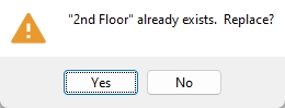
Alternative 1: If the name in the Erection view name field matches an existing erection view, you will be prompted to verify the replacement of the existing view. Click Yes to replace the existing view. Click No to cancel the replacement and end the command.
Alternative 2: Click Cancel to close the Name Required window and end the command.
- Saved Area allows you to work in partial areas of the total 3D model.
- Another reason to create an area view is so you can later regenerate it as an erection view drawing and then place it on a sheet for printing.
- Partial views of a 2D drawing can be created using Viewport Add as an alternative to saving partial 3D erection views.
- If you want to save a view that includes all steel in your current view, use Save View As.
- If you use an existing view's current name, the existing view can be replaced with the current view.
- The display current view decoration shows the current view you have open.
- If Erection view operations is checked ( ) in Home > Project Settings > Job > Modeling > Event Logging, changes to an erection view that are saved using Save Area (renaming, elevation changes, etc.,) will be logged as a Job event. The
 Log
Log
- Point selection by area box (affects Save Area)
- Depth checking (affects Save Area)
- Drawing scale (alternative to scale set with Save Area)
- Rename Project Items (to change a view's name)
- Rename (selection dialog button for changing a view's name)
- Display current view (decoration that displays current view's name)
- Constructing the 3D Model (topic)
- Detail Erection Views (to create 2D drawing of area view)

